Contact us on

1.Structural features
Rubber bends are especially designed from an imperfect sphere transitting to a straight pipe which accords with the principle of fluid mechanics. Not only the production pause problem in the process flow of mines, electric power plants and chemical industry can be settled fundamentally but also quick abrasion on bends and large friction and serious power consumption are settled. The movable flange equipped is handy to connect. They can be divided into rubber spherical bends and steel bends lined with rubber under high pressure according to working pressure.
Range of application: It is suitable for conveying all slurry and chemical corrosive medium.
2.Characteristics
●Wear resistance, long service life
●Steel flanges at both sides of the bends are movable and it is handy for the pipe flange on the both sides of the pipe to connect. Even though the pipeline is not fitted up ideally and the bends can be fixed. The dummy club at the both sides of the bend can be used as flange spacer and seal more tightly utilizing the resilient wearablerubber.
●At the corner of middle part of the bend ,there is a sphere that can avoid fluid abrading bends and avoid resistance for fluid, and at the same time, the air in the pipe can breath at this part.
●Rubber bends are lighter than steel bends and easy to fix and replace.
3.Type of bends
There are two types of rubber bends: one is molded bend LWT/M which is wholly made of rubber and working pressure should be less than 0.6Mpa. The other is steel bend lined with rubber LWT/G and its shell is made of steel and the liner is wearable rubber. Its working pressure should be less than 1.6Mpa.
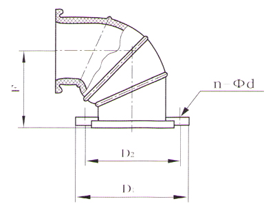
4.Structure and dimension
LWT-M type Wear elbow spherical Jiaozhi main technical parameters and flange size table
| Nain parameter | flange dimension (standard flanger) | |||
| DN | F | D1 | D2 | n-Φd |
| 50 | 65 | 165 | 125 | 4-Φ18 |
| 65 | 85 | 185 | 145 | 4-Φ18 |
| 80 | 105 | 200 | 160 | 8-Φ18 |
| 100 | 130 | 220 | 180 | 8-Φ18 |
| 125 | 165 | 250 | 210 | 8-Φ18 |
| 150 | 198 | 285 | 240 | 8-Φ22 |
| 200 | 264 | 340 | 295 | 8-Φ22 |
| 250 | 330 | 395 | 350 | 12-Φ22 |
| 300 | 396 | 445 | 400 | 12-Φ22 |
| Nain parameter | flange dimension (standard flanger) | |||
| DN | F | D1 | D2 | n-Φd |
| 50 | 65 | 165 | 125 | 4-Φ18 |
| 65 | 85 | 185 | 145 | 4-Φ18 |
| 80 | 105 | 200 | 160 | 8-Φ18 |
| 100 | 130 | 220 | 180 | 8-Φ18 |
| 125 | 165 | 250 | 210 | 8-Φ18 |
| 150 | 195 | 285 | 240 | 8-Φ22 |
| 200 | 260 | 340 | 295 | 12-Φ22 |
| 250 | 325 | 405 | 355 | 12-Φ26 |
| 300 | 390 | 460 | 410 | 12-Φ26 |
For general enquiries call our Customer Service Centre on
For website enquiries call our eBusiness Support on or send an email